TYPES OF HEAT TREATMENT OF STEELS

. purpose of heat treatment

. purpose of annealing

. difference between the processess of annealing and normalising

The properties of steel depend upon its composition and its structure. The properties of steel and its structure can be changed by heating it to a particular temparature and then, allowing it to cool at a definite rate. The process of heating and cooling for changing the structure of steel,and thus obtaining the required properties is called 'heat treatment of steel'.

If steel is heated to a suitable temaprature, and then, slowly cooled, the steel will be soft, weak and ductile.

If steel is heated to a suitable temaprature, and then, rapidly cooled (quenched) the steel will be hard and brittle.

Classification of heat treatments

The treatments that produce equilibrium conditions are annealing and normalising.

Treatments that produce non-equilibrium conditions are hardening and tempering (usually done in conjunction with each other)

Annealing

In this process, steel is heated to a suitable temparature depending upon its carbon content, and is held at that temparature for sufficient time, and then slowly cooled to room temparature.


The heating, soaking (holding the room temparature )and slow cooling cause the grains to become large, and so produce softness and ductility.

For annealing, hypoeutectiod steel is heated to 30° to  50°c above the upper critical temparature,and it is 50°c above the lower critical temparature for hypereutectoid steel.

Soaking time at temparature is 5mts/10 mm of thickness for carbon steel.

The cooling rate for carbon steel is 100 to 150°C/hour.

The cooling is done in the furnace itself by switching off the furnace or the steel is covered either in sand or dry lime  and dry ash.

ANNEALING TEMAPRATURE

carbon content %         temaprature °c

< 0.12                                 875 to 925

0.12 to 0.25                       840 to 970

0.25 to 0.50                       815 to 840

0.50 to 0.90                       780 to 810

0.90 to 1.3                         760 to 780

Purpose of annealing

Annealing is done

- to obtain softness

-to improve machinability

-to increase ductility

-to relieve internal stresses

-to reduce or eliminate structural inhomogenity

-to refine the grain size

-to prepare the steel for subsequent heat treament process.

Normalising

Due to continuous hammering or uneven cooling, strains and stresses are formed in the internal structure of steel. These should be removed from forgings or castins. Otherwise, they may fail at any time while in use.

Normalising is done to produce a fine grain for uniformly of structure and for improved machanical properties.

The normalising process

In this process, steel is heated to a suitable temaprature depending upon its carbon content, and held at that temparature, and then cooled freely in air.

Normalising is usually done, before machining and before hardening, to put the steel in the best condition for these operations.


The steel is heated to a temaprature (30 to 40° c above the upper critical temparature )at which all the austenite is present even in  the case of high carbon steel. This is because this process is the first step towards producing the final properties, and it is necessary to start with austenite to ensure uniformly.

PRECAUTION

The heated piece for normalising should not be kept at any wet place, in wet air or kept in forced air as they will induce some hardness 


Heating and cooling process of steel

. structural changes of plain carbon steel while heating

. the structural changes of plain carbon steel in normal cooling

Distinguish between the lower and upper critical temparature during heating and cooling.

Heating

While heating uniformly a piece of plain carbon steel in a furnace, the temparature will increase uniformly and it will be halted or will fall slightly for a short time although the heat is supplied to the steel.

At this point, the heat, is being used to  cause a rearrangement of the iron atoms which, in turn,, causes the formation of a solid solution called austenite.

The temparature at which austenite is formed is called the lower critical point (heating ) and is at 723°c.

If the steel contains less than 0.83% carbon there will be some ferrite present after the above change also. And if it contains more than 0.83% carbon, there will be some cementite present after this change.

If the heating is further continued, the ferrite or cementite present will be gradually tranformed into austenite. Less heat is required for this page.


The  temparature at which the formation of austenite is total called the upper critical point(heating ).

The temparature of upper critical point(heating )  depends upon the percentage of carbon in steel.

Cooling

While cooling, the temparature of the piece will fall uniformly untill a certain temparature is reached at which stage it starts to cool less rapidly.

The temparature at which the above is happening is called the upper critical point (cooling ) and is 30° c below upper critical point (heating ).

At this stage the austenite starts to break down to produce either ferrite or cementite according to the percentage of carbon in the steel.

The total breaking of the austenite to ferrite or cementite will continue untill the lower critical point (cooling )is reached at 693° c.

Then there will be a halt in the decrease of temparature. This halt in temparature willl be utilised for the breakdown of austenite caused by the rearrangement of the iorn atoms.


This rearrangement reduces heat which causes the changes in the rate of fall of the temparature of the steel.


The changes observed during this heating and cooling of steel are important in the study of its heat treatment. The changes indicated are those that occur when the steel is COOLED SLOWLY and the diagram is accordingly called a thermal equilibrium diagram. It is usual to indicate the temparature at which the changes occur during cooling, the changes also occur during heating, but the temparature at which they  occure are all 30° c higher than those associated with cooling.


METHODS OF IDENTIFICATION OF METALSS

.The different methods of identifying ferrous metals and alloys

. state how non ferrous metals and alloys are identified

A fitter has to handle different types of metals in his  work. A knowledge about how to recognise and differentiate the commonly used metals will help him in many ways.

Ferrous metals and alloys can be identified by

Their appearance (colour, texture etc,)

Their weight (light or heavy )

The sound

Cold hammering

The spark test (grinding )

Apart from the above tests steel bars are also identified by the code colours painted on them.

Different colours are marked, based on the different composition of materials and grade. Colours charts are available to determine the different metals.

Most non ferrous metals and alloys can be identified by their colour.

copper colour is distinctive red colour

Aluminum colour is  dull  white

Lead colour is bluish grey colour

Tin colour is silvery white, with a slightly yellowish tinge

Brass colour is distinctive yellow colour

Bronze colour is colour between copper and brgiven


Characteristics of different ferrous metals and alloys given

Low carbon steel

The appearance is smooth scale with blue/black sheen/silver grey. The density and weight is 7.85 medium weight. The sound (drop  a 15 to 25 cm long, on to the ground ) is medium metalic sound. The cold hammering is flattens easily. The spark test is stream of  yellow white sparks varying in length slightly fiery.

Medium carbon steel

The appearance is smooth scale black sheen. The density is 7.85 and weight is medium weight. The sound is higher note than that of low carbon steel. Cold of hammering is fairly difficult to flatten. The spark test is yellow  sparks shorter than those of low carbon steel, finer and more feathery.

High carbon steel

The appearance is rougher scale black. The density of metal is 7.85 and weight is medium weight. The soundof metal is good ringing sound. The cold hammering is difficult to flatten. The spark test is sparkless bright, starting near grinding wheel and more feathery with secondary branching.

High speed steel

The appearance of metal is roughness scale black with reddish tint. The density of metal is 9 and the weight is comparatively heavy. The sound of a metal is lower ringing more like low carbon steel.. The cold hammering is very difficult to flatten tends to crack easily. The spark test is faint red streak ending in fork.


Most use manufacturing process of steel?

The principle of the L. D converter

Name the raw materials used for the charge in L.D process👍

L. D. Process

The name L.D. is derived from the initials of two towns,LINZ & DONAWITZ in Austria where this process was first used.

The L. D. is converter or the basic oxygen converter is designed to produce high quality steel in a relatively shorter time. The basic raw material used in the process are the molten pig iron from the blast furnace and the steel strap. Fluxing agents are used for reacting with impurities and form a slag on the top of the molten metal.


In this process of 👍producing steel, a jet of pure oxygen is blown through a lance which is water cooled.The lance is brought near the molten metal and oxygen is blown at high pressure on the molten metal bath. This leads to the oxidation of carbon and other impurities causing violent agitation which allows all the molten metal to come in contact with the oxygen stream. When the blowing is over,the converter is tipped to remove the slag and again turned the other way to collect the metal into a ladle.

Controlled quantity of carbon and other elements are added to obtain the desired quality of steel.

Electric process

Two types of electric furnace are in use

-electric arc furnace

-high frequency furnace

High grade steels and alloy steels are made by the electric process

No fuel or air is required for burning. Because of this there is no contamination of the charge.

Electric arc  furnace

In this type of furnace, the heat required is generated by electric arcs struck between carbon electrodes and the metal bath. This type of furnace is used for making alloy steels, such as stainless steel, high speed steel etc.


The composition of the steel can be accurately controlled in this process. This process is not influenced by the external conditions and the temparature of the furnace can be maintained to the desired level.

The furnace uses pig iron and selected scrap, and produces high quality steel.

When the metal is molten and the slag is formed on the top surface, the furnace is tilted and the slag is removed. Then the furnace is again tilted in the other way to collect the molten metal. Silicon, manganese and other necessary elements are added in the ladle, and the composition of steel regulated.

The high frequency furnace

This furnace consists of a crucible made of refractory materials, surrounded by an inductor coil which carries the alternating current, and is insulated and water cooled. The outer ring is made of special magnetic iron laminations,, and shields the casting from getting too hot. It also serves as a magnetic sheild to increase the magnetic flux in the coil.


The charge used consists of steel scrap and iron oxide.

The steel is further refined by re melting and addition of the required alloying elements. Steel, produced by these processes, is used for making press tools, cutting tools and precision measuring instruments.

OPEN HEARTH PROCESS

This process eliminates the  disadvantage of the Bessemer process. Most of the steel in our country is produced by SIEMENS MARTIN process using an open hearth furnace.

Open hearth furnace

An open hearth furnace is a reverberatory furnace, having a melting chamber built with refractory materials, bounded at the top the roof, and at the bottom by the hearth. The charging doors are provided at the side walls. The melting area is connected with regenerators through ports.

Fuel for this process is the producer gas generated by a plant which can be fed  to the hearth through two generating Chambers. The air, which forms a combustible mixture, may be fed the same way through the other two chambers

Heating through producer gas and air is the characteristic of the open hearth furnace. For the chemical reaction of the charge, intense heat is required. This can be achieved through regenerating chambers.

The process

The hearth is first prepared and heated  well up to 1500°c. The charge is a mixture of pig iron and steel scrap in different proportions as required according to the class of steel to be manufactured.

The ratio of pig iron to scrap varies from 1:4 to 4:1 A reasonable ratio is 3:2. After the charging is over, the gas is allowed in to the melting champer. During melting, part of  the carbon, most of the silicon and  manganese are removed by oxidation. More carbon will be oxidised away at the  boil stage by adding iron ore to the charge. When the bath reaches the requisite percentage of carbon, the furnace is allowed for tapping. While the metal is flowing into the ladle, a de-oxidiser is added to the steel to remove air, and ensure soundness in the metal.


Manufacturing process of steel by Bessemer process ok on on

.The different manufacturing processes of steel

. manufacturing process of steel by the bessemer process

. distinguish between acid process and basic process

Manufacturing processes

The different manufacturing processes of steel

-Bessemer process

-L. D process

-Electric process

-Open hearth process

Bessemer process

Sir Henry Bessemer, a British engineer invented this process of converting molten pig-iron to steel  using a large pear shaped container. This is called the Bessemer converter.


It is a method of producing steel by blasting compressed air through molten iron and burning out the excess carbon and other impurities. This does not use any source of heat other than obtained from the oxidising process used to remove carbon and other impurities.

The three stages of this process are

-the preliminary stage

(The slag formation )

-the boil stage

(The brilliant flame blowing period)

-the finishing stage

(The reddish smoke period )

The molten pig iare from the blast furnace is poured into the converter. Then the blast of air at 150 to 250 KN/m2(killo Newton /m2) is directed into the molten metal, and the converter is rotated into an upright position. The conversion stage  commence now.


At the preliminary stage, the oxygen of the blast oxidises the iron to ferrous oxide. As a slag, the ferrous oxide mixes with the metal. The silicon and manganese, due to their affinity for oxygen, are seperated as oxides and go into the slag. During this reaction, a large amount of heat is generated which increases the  temparature from  1250°c to 1525°c. This stage lasts for 3 to 4 minutes.

The 2nd stage helps the burning of carbon from the molten bath. The  dissolved carbon is oxidised by the ferrous oxide of the slag. At the same time, carbon monoxide will be burning at the nose of the converter with a dazzling white flame. This elimination of carbon takes place for about 8 to 12 minutes. The 3rd stage starts with the subsiding of the flame. It means that the carbon  has been practically removed from the charge. This stage lasts  for one or two minutes. Then the converter is brought to a horizontal position. To eliminate oxygen and to bring silicon, manganese and carbon content of the steel to a specific limit, de oxiders like ferro manganese, ferro silicon or aluminum are added to the metal bath.

The Bessemer process has  the following disadvantages.

The steel produced by the Bessemer process will have an increased oxygen content which will impair its mechanical properties. Due to this reason, it cannot be used for producing cutting tools, spring and parts subject to impact, load etc..

When the Bessemer converter is line with silicous refractory material,this process is called acid process.

When the converter is  lined with a basic refractory, it is called a basic process or thomas  process.


Methods of coloring of metals

 Colouring of metals

.methods of colouring by heat

.different methods of colouring metals

. method of blackening /black oil finishing of metal surfaces

Machined or filled ferrous metal  surfaces can be colored by the following methods.

Heating and cooling

Application of chemicals

Colouring by heating

Attractive colours can be given to metals by  heating. In this process, the metal surface to be treated is thoroughly polished.

The metal is then placed in a heat treatment oven or flame heated.

During the heating of the metal, watch the colours as they appear.

When the desired colour is seen, remove and quench suddenly in water or oil.

Rub gently with steel wool.

Black oil finish

For blackening the surface of a ferrous metal, first clean the surface thoroughly, and apply a coating of thick lubricating oil.

Then heat the metal to 150° to 175° c for about 5 to 8 minutes.

This will give a black and rust preventing coating on ferrous metal surfaces.

Chemical colouring

Polished surfaces of iron and steel can be given the following colours by the application of certain chemicals.

Colour and process

BLUE BLACK 

Process- Mix 16 parts of saltpetre and two parts of oxides of manganese. Heat the mixture to 400° c and dip the cleaned work in it. Keep the workpiece in the mixture and allow it to cool.

BROWN 

Proces- Dip the workpiece in ammonia and dry in open air. Dip the work in hydrochloric acid and dry in warm place. Dip the workpiece in gallic acid and remove it when the desired colour is obtained.

BRONZE

Heat the workpiece slightly and paint a paste of antimony chloride. Watch for the desire shade to appear on the workpiece. Then wipe it dry.

CAUTION

Use hand gloves and goggles when working with chemicals.

Steel ( Plain carbon steel)

Steel is fundamentally an alloy of iron and carbon with the carbon content varying up to 1.5%. The carbon present is in a combained state.

Plain carbon steels are classified according to their carbon countent.

CLASSIFICATION AND CONTENT OF PLAIN CARBON STEEL

DEAD MILD STEEL

The percentage of carbon is 0.1 to 1.25%.

They high ductile. Used for making wire rods, thin sheets & solid drawn tubes.

MILD STEEL

The percentage of carbon is 0.15 to. 3%.

They relatively soft and ductile. Used for general workshop purposes,boiler plates, bridge work, structural sections and drop forgings.

MEDIUM CARBON STEEL

The percentage of carbon is 0.3 to 0.5%.

Used for making axles, drop forgings, high tensile tubes, wires and agricultural tool.

Medium carbon steel is carbon percentage different 0.5 to 0.7%.

This medium carbon steel is used for making steel,locomotive tyres, large forging dies, wire ropes, hammers and snaps for riveters

HIGH CARBON STEEL

High carbon steel is percentage of carbon 0.7 to 0.9%  is used  for making spring, small forging dies, shear blades and wood chisels.

High carbon steel percentage of carbon is 0.9 to 1.1%. It is used for making cold chisels, press dies, punches, wook working tools, axes etc.

High carbon steel percentage of carbon 1.1% to 1.4% is used for making hand files, drills, gauges, metal cutting tools,razors.


Principle of metal cutting


.different angles formed at the cutting edge of tools

. the important of clearance and rake angles in metal cutting

Metal cutting

Knowledge about the principal for metal cutting relating to the various tool angles will assist in carrying out of metal cutting work efficiently.


Workpiece are shaped and brought to the required dimension by the use of cutting tools. While cutting materials the following four important elements interact.

Cutting tool

Tools holding or grinding device

Work holding devices, and work

Although the metal cutting process involves the combination of the above four elements, everything begins with a cutting tool and its impact at the time of contacting the workpiece.


The common metal cutting processes are carried out either by the  use of a single point or multi point cutting tools.

Cutting edge are taken as the factors for determining the tool life, surface finish, and the force required for cutting.

The important angles of the cutting edge are

Clearance angle

Rake angle

Wedge angle or tool angle


Clearance angle

This is the clearance or relief provided behind the cutting edge.


If the clearance angle is not provided the tool will rub against the work surface, and will impose a lot of strain before the metal chips are sheared from the work.

The clearance angle improves these conditions and prevents tool rubbing, thus reducing the cutting force.

The clearance angle depends on the of surface being machined.

Normal clearance angles for different surface are

External cylindrical surface    -5° to 7°

Flat surface                                  -6° to 8°

Internal cylindrical surface      -8° to 10°

Smaller clearance angles tend to rub against the surface while excessive clearance causes chatter, and there  is a tendency for the tool to dig in. This will also result in increased tool angle thereby reducing the tool strength.

Rake angle

This is the angle given in the front of the leading edge of the tool.

This reduces the pressure of the chip on the tool face, and thereby reduces the cutting force ;also, it affects the formation of chips and the surface finish.


Positive rake angles produce better finish at low speeds.

Increased rake angle increases the cutting efficiency but decreases the tool wedge angle, and thereby decreases the strength of the tool. Low strength and ductile materials can be cut with increased efficiency with tools having high rake angles.High strength materials are cut with tools having high rake angles. Low strength materials are cut with tools having low positive rake angles.

Zero and negative rake angle tools are stronger and have a long tool life.


Negative rake tools produce poor finish at low cutting speeds but give good  finish at higher cutting speeds

Negative rake tools need more power to operate than the positive rake tools.

Rake angle of different metals

Cast iron 0°

Ductile brass 14°

Free cutting brass 0°

Tin bronze 8°

Aluminium alloys 30°

Mild steel 25°

Medium carbon steel 25°

High carbon steel 12°

Teflon 0°

The wedge or tool angle is affected by the amount of clearance and rake angle. More clearance and rake angle will decrease the tool wedge angle thereby reducing the strength of the cutting edge.

The rigidity of tool holders and holding devices contributes to efficient cutting.

The design of the holder depends on the type and shape of the tool and its intended function.

The work holder used depends on the shape of the work and the type of force acting during cutting.


Types of metal cutting saws

Different types of cutting saws

Advantages of a horizontal band saw

Different types of cutting saws

Metal cutting saws of different types are used in industries. The most commonly used are the

Power saw

Horizontal band saw

circular saw

Contour saw

Power saw

This is the most commonly used metal cutting saw.


Horizontal band saw

This has a saw frame on which a motor is  fitted. There are two pulley wheeels on which an endless band saw passes.

Speed variation is obtained through the stepped pulleys on the motor.


The roller guide brackets provides the rigidity for the blade in the cutting area and also prevent wandering of the blade while cutting.

The blade tension is maintained by using the adjusting handle, provided for this purpose.

A vice is provided for holding the metal stocks. The vice is adjustable for angular cutting.

The machine has the advantage of continuous cutting ability, and is much faster than a power saw. It may be noted that a power saw cuts only in every alternate stroke.

Circular saw

This type of cutting machine is used  when cutting materials have a large cross section. The circular saw has a continuous cutting action and is economical in production work where heavy section metals are used.


Contour saw

In this a metal band saw blade is used, and the contour saw has a continuous cutting motion.

These machines are very much used for cutting metals to different profiles.

Different speeds can be obtained while cutting, with the help of variable speed pulleys.


For repairing broken countour saw blades, these machines are fitted with a  shear for trimming the blade ends, a but welding machine for joining the ends and the small grinder to finish the welded joint.


The table can be tilted t any angle for angular cutting. The blades passes through a guide which prevents the blades from wandering and keep it rigidity.

These machines are widely used for tool room work, and not as a machine for cutting raw material stock.

Precautions while machine sawing

In order to work safely and efficiently, certain precautions are to be obserened.

While taking measurements of the work for setting,always stop machine.

Projecting ends of the work should be well guarded, so that safety may be provided to others.

Ensure that the work does not protrude into the gangways.

When sawing thin pieces, hold the material flat in the vice to prevent the saw teeth from breaking.

Ensure a cutting fluid is used always.

Avoid giving excessive cutting pressure, because this can cause breakage to the blade, and cut work out of square.

When several pieces of the same length are to be cut, use a stop gauge

When holding short workpiece in a vice, be sure to place a short piece of the same thickness in the opposit end. This will prevent the vice from twisting when it is tight ened


POWER HACKSAW

Features of power hacksaw

features of a power hacksaw

. correct blade of different types

. features of power hacksaw blade


Cut-off saws are used to cut metal stock roughly to the required length. 🤺 commonly used to cut off saw in small scale industries is a POWER SAW.

Power hacksaw

Features

The power saw works like a handsaw, and has an arrangement for cutting during the movement in one direction and releasing pressure on the non-cutting stroke. The rotary motion of the motor is converted into linear motion by a crank mechanism.

The required cutting pressure is obtained hydraulically or by an adjustable weight.

During the non-cutting motion the blade will be lifted away from the work.

A clamping device /vice holds the work firmly.

Power hacksaw blades

The saw blades are selected, depending on the machine and the type of work on hand. The blades are made of H. S. Steel and are fully hardened.

For different materials, blades of different pitches are used (number of teeth per 25mm length ).


As a general rule, the softer the material, the lesser  is the number of teeth, per length of 25mm.

Teeth with a large pitch can accommodate large chips.

Blades are available with varying coarseness i.e between 4 to 14 teeth per 25 mm length.

Coarse pitch blades are also used while cutting large sections of stock, as this will help in greater chip clearance  and increased penetration.

For cutting hard material, and thin material, a 14 pitch blade is recommended.

For general purpose sawing, a 10 pitch blade will be useful.

While selecting blades, make  sure atleast two teeth of the blade will be in contact with the work at all times.

What will happen if less than two teeth are  in contact with the work?

The work can be caught in the tooth gullet, and cause breakage to the blade.

Blade clearance

In order to avoid jamming of the teeth and to provide for chip clearance, the teeth of the saw bladers are offset or waved.


SPECIFICTION OF POWER HACKSAW BLADES

while specifying power hacksaw blades, it is necessary to state

-the length (distance between centre of holes)

-the width

-the thickness and

-the teeth pitch

Clamping arrangement

Power saws are provided with clamping devices similar to those in machine vices, and the work can be gripped by using the crank  handle.


When a number of pieces of the same size are to be cut, an adjustable stop is used.

Long bars are supported, and the level maintained by the use of adjustable floor stands.


Fixing blades

The blades are mounted on frames using screws.

The teeth of the blade should point towards correct direction. (Depending on the type of machine the blade either cuts on the forward or on the return stroke).

It is necessary to follow the directions given by the manufactures as indicated in the frame.

Tension the blades using the tensioning device.


Small hole measuring gauges

. parts of a telescopic gauge

. constructional features of telescopic gauges

. parts of a small hole gauge

Telescopic gauges are popular for fine work as they are very rigid and have a better 'feel'.

Uses

Used for measuring the sizes of holes, slots and recesses.

Construction


Telescopic gauges are 'T' shaped. They consist of a pair of telescopic legs or plungers connected to a handle. The plungers are spring loaded to force them apart. After inserting the gauge in a hole or slot, it can be locked in position by turning the knurled handle. It may then be withdraw from the hole and measured with a micrometer.


Telescopic gauges are available in a set of 5 nos, to measure holes from 12.7mm to 152.4mm.

No.1 12.7mm to 19mm

No.2 19.0mm to 31.7mm

No.3 31.7mm to 53.9mm

No.4 53.9mm to 88.9mm

No.5 88.9mm to 152.4mm

Small hole gauges

Telescopic gauges are not suitable for measuring holes below 12.7mm. For measuring smaller holes and slots, small hole gauges are used.

Construction

A small hole gauge consists of tube having holes on the opposit sides at one end where hardened balls are fixed. The other end of the tube has an external thread. A screwed thimble is fixed with a threaded ttube. A plunger with a tapered end, and spring loaded, is in serted in the tube and tightened with the screwed thimble. At the end of the thimble a knurled handle is fitted. While rotating the knurled handle in a clockwise direction the plunger moves forward up, and pushes the balls out to contact the surfaces


.

A small hole gauge is an instrument used for indirect measurement, while a micrometers is usually used for measuring the sizes.

Small hole gauges are available in a set of 7 numbers to small hole gauges are available in a set of 7 numbers to measure holes from 3.2mm to 12.7mm.

No. 1 3.2mm to 3.8mm

No. 2 3.8mm to 4.5mm

No. 3 4.5mm to 5.1mm

No. 4 5.1mm to 6.4mm

No. 5 6.4mm to 8mm

No. 6 8mm to 9.6mm

No. 7 9.6mm to 12.7mm

Uses of wrought iron

Wrought iron

manufacturing process of wrought iron

. properties and uses of wrought iron

Wrought iron is the purest form of iron. The analysis of wrought iron shows as much as 99.9% of iron.

When heated, wrought iron does not melt, but only becomes pasty and in this form it can be forged to any shape.

Modern methods used to produce wrought iron in large quantities are the

-pudding process

-aston or byers process

Pudding process

Wrought iron is manufactured by refining pig-iron.

By refining pig-iron silicon is removed completely, a greater amount of phosphorus is removed, and graphite is converted to combined carbon.

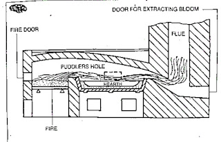
The above process is carried out in a pudding furnace.

Pudding furnace

This furnace is a coal-fired reverberatory furnace.


The term reverberatory is applied because the charge is not in actual contact with the fire, but receives its heat by reflection from the dome shaped furnace roof.

The product obtained is taken out from the furnace in the form of balls (or blooms) having a mass of about 50kgs.

The hot metal is then passed through grooved rollers which convert blooms into bars called MUCK BARS or PUDDLE BARS.

These bars are cut into short lengths, fastened together in pilers, reheated to welding temparature and again rolled into bars.

Aston process

In this process molten pig iron and steel scrap are refined in a bessemer converter.

The refined molten metal is poured into an open hearth furnace in the iron silicate stage. This removes most of the carbon.

The slag cools the molten metal to a pasty mass which is later squeezed in a hydraulic press to remove most of the slag. Rectangular blocks known as blooms are formed from this mass.

The hot bloom is immediately passed through rolling mills to produce  products of wrought iron of different shapes and sizes.

COMPOSITION OF WROUGHT IRON

Carbon     - 0.02 to 0.03%

Silicon      - 0.1 to 0.2%

Manganese -  0.02 to 0.1%

Sulphur      - 0.02 to 0.04%

Phosphorus - 0.05 to 0.2%

Iron forms of the rest of the content.

PROPERTIES AND USES OF WROUGHT IRON

PROPERTIES

Malleable and ductile. It can neither be hardened not tempered. Tough, shock resistant fibrous structure easy for forge welding. Ultimate tensile strength of about 350 newtons per sq. mm. No effect in salt water. Will not retain the magnetism. Corrosion resistant. Easy to forge wide temparature range 850° c to 1350° c.

USES

Architectural works.

Crane hooks, chain links, bolts and nuts and railway coupling.

Marine works.

Temporary magnets. Core of dynamos.

Agricultural equipment.

Pipes, flanges etc.

SURFACE PREPARATION

Surface carrying dirt, grease, corrosion or mill scale are unsuitable for the direct application of anti corrosion treatment.

The most important factor for any efficient anti corrosion treatment is surface preparation.

The different methods  used for surface preparation are:

--degreasing

-pickling

-blast cleaning

-flame descaling

Degreasing

In degreasing, the surface preparation for anti corrosion treatment is done with a solvent such as:

-white spirits

-carbon tetrachloride

-trichlorethylene

The solvents used in degreasing will create a health hazard. Safety precaution should be taken before using these solvents.

Pickling

Pickling is a chemical method of cleaning.

The surface of the metal is cleaned with dilute sulphuric acid or mixed acids.


Blast cleaning

This is a mechanical method of a cleaning in which the scale and corrosion are removed by a high velocity blast of steel shots or sand particles.If steel shorts are used it is called sand blasting.


Flame descaling

The steel surface which is to be descaled, is heated with an oxy-fuel gas torch with high intensity flames.


This rapid local thermal expansion of  the loosely adhering scale against the relatively un heated base metal causes the scale  to flake off.

This process is excellent for removing rust. Any rust particles converted to powder can  easily be brushed away before commencing to paint. For best results the primer should be applied when the steel is approximately 45°c, that is the temparature at which the hand can hold the steel comfortably.

This method of surface preparation is often specified for the heavy rusted steel work. It is not suitable for light steel work which may buckle and distort because of the intense localized that.


Different Types of cast iron

. different types of cast iron

. properties of each type cast iron

Cast iron is an alloy of iron, carbon and silicon. The carbon content ranges from 2 to 4%.

Types of cast iron

The following are the types of cast iron.

-Grey cast iron

-White cast iron

-Malleable cast iron

-Nodular cast iron

Grey cast iron

This is widely used for the casting of machinery parts and can be machined easily.

Machine bases, tables, slideways are made of cast iron because it is dimensionally stable after a period of  aging.

Because of its graphite content, cast iron provides an excellent bearing and sliding surface.

The melting point is lower than that of steel and as grey cast iron possessses good fluidity intricate casting can be made.

Grey cast iron is widely used for machine tools because of its ability to reduce vibration and minimize tool chatter.

Grey cast iron, when not alloyed, is quite brittle and has relatively low tensile strength. Due to this reason it is  not used for making components subjected to high stress or impact loads.

Grey cast iron is often alloyed with nickel, chromium, vanadium or copper to make it tough.

Grey cast iron is weldable but the base metal needs preheating.

White cast iron

This is very hard and is very difficult to machine, and for this reason,, it is used in components which should be abrasion-resistant.

White  cast iron is produced by lowering the silicon content and by rapid  cooling. When cooled in this manner, it is called chilled cast iron.

White cast iron cannot be welded

Malleable cast iron

Malleable cast iron has increased ductility, tensile strength and toughness when compared with grey cast iron.

Malleable cast iron is produced from White cast iron by a prolonged heat treatment process lasting for about 30 hours.

Nodular cast iron

This is very similar to malleable cast iron. But this is produced without any heat treatment. Nodular cast iron is also known as

NODULAR IORN -DUCTILE IRON- SPHEROIDAL GRAPHITE IRON.

This has good machinability, castability, resistance to wear, low melting point and hardness.

Malleable and nodular casting are used for machine parts where there is a higher tensile stress and moderate impact loading. These casting are less expensive and are an alternative to steel casting.

Cast iron manufacturing process

The pig iron which is tapped from the blast furnace is the crude form of raw material for the cupola, and should be further refined for making castings. This refining is carried out in the cupola furnace which is a small form of  a blast furnace.

Generally cupolas are not worked continuously like blast furnaces but are run only as and when required.

Working of a cupola

For starting a cupola, a COKE fire is lit at the bottom of the cupola. When the fire is established, the furnace is charged with alternate layers of coke and pig iron together with limestone. Steel scrap is also sometimes added depending on the required quality of metal. Adding steel scraps with a lower carbon content reduces the carbon content in the metal. During melting, a blast of air is also introduced into the furnace.

The molten limestone combines with sand and other impurities and floats in a liquid form on the top of the molten metal. It is called slag.

The molten metal sinks to the bottom of the furnace from where it is tapped and collected in ladles. The hot metal.

Uses of pig-iron

.commonly used ferrous metals

. main raw materials used for the smelting of pig-pron and their uses

. constructional features of  a blast furnace


. properties and uses of pig iron

Metals which contain iron as a major content are called ferrous metals. Ferrous metals of different properties are used for various purposes.

The ferrous metals and alloys used commonly are

-pig iron

-cast iron

-wrought iron

-steel and alloy steels

Different processes are used to produce  iron and steel.

Pig-iron obtained by the chemical reduction of iron ore. This process of reduction of the iron ore to pig-iron is known as SMELTING.

The main raw accoutrements needed for producing gormandizer-iron are 

-iron ore

-coke

-flux

IRON ORE

The cheif iron ores used are

-magnetite

-hematite

-limonite

-carbonite

These ores contain iron in different proportions and are 'naturally ' available.

COKE

Coke is the fuel used to give the necessary heat to carry on the reducing action. The carbon from the coke in the form of carbon monoxide combines with the iron ore to reduce it to iron.

FLUX

This is the mineral substance charged into a blast furnace to lower the melting point of the ore, and it combines with the non-metalic portion of the ore to form a molten slag.

Limestone is the most commonly used flux in the blast furnace.

BLAST FURNACE

The furnace used for smelting iron ore is the blast furnace. The product obtained from smelting in the blast furnace is pig-iron. The main parts of the blast furnace are

-throat

-stack

-bosh

-hearth

-double bell charging mechanism

-tuyeres

SMELTING IN A BLAST FURNACE

The raw materials are charged in alternate layers of iron ore, coke and flux in the furnace by means of a double bell mechanism.


The hot blast is forced into the furnace through a number of nozzles called tuyeres.

The temparature of the furnace just above the level of the tuyeres is between 1000°c to 1700° c when all the substance start smelting.

The limestone, which serves as a flux, combines with the non metalic substances in the ore to form a molten slag which floats on the top of the molten iron. The slag is tapped off through the slag hole.

The molten iron is trapped at intervals through a separate tapping hole.

The molten iron may be cast in pig beds or used in other processing plansts of steel making.

PROPERTIES AND USE OF PIG-IRON

Pig iron absorbs varying amount of carbon,silicon, suphur, phosphorus and manganese during the smelting process. A high amount of carbon makes the pig-iron very hard and brittle and unsuitable for making any useful article.

Pig iron is therefore refined and remelted and used to produce other varieties of iron and steel.


Types of plastics

Plastics

. types of plastics

. differentiate between thermoplastics and thermosetting plastics


The dictionary meaning of plastic is 'capable of being easily formed or moulded'.

There are a number of synthetic materials available under the name of plastics.

Plastics have their origin in the chemical synthesis of materials from different sources like

-agriculture

-agriculture and petroleum

-petroleum and coal

-petroleum and mineral

-minerals

Of these, coal and petroleum are mostly used in making plastics

Plastics are divided into three major categories

-thermoplastic

-thermo-setting plastics

-elastomers

Thermoplastics

These are formed into shape by the application of heat and pressure. They soften when heated, and become solid agian when cooled. There is no chemical change in the moulding operation.

Thermoplastics are

-nylon

-polythene

-polypropylene

-polystyrene

-poly vinyl chloride

-acrylic resin

-cellulose

Nylon(polymide)

It is strong, tough and of light weight. It has a good abrasion resistance, and resistance to chemicals, fuels and oils.

It is used for making light engineering components such as gears, bushes, bearings, machine slides, rollers, brush bristles etc.

Polythene

There are two types

-low density polythene

-high density polythene

Polythene is cheap. It has high resistance to water, oils and chemicals. It can also withstand sizable temparature changes.

Low density polythene is used for making bags, sacks for package, dust bins, toys and house wares etc.

High density polythene is used for large moulded containers, bottles, milk crates, pipes and better quality House-wares.

Polypropylene

It is the lightest among plastics. It is tough and has high resistance to heat and chemicals.

It is used for making automobile accelerator pedals,suitcases, hospital equipment, ropes and twines etc.

Polystyrene

It is the cheapest, had good resistance to water, oils and alkalis. But it disolves in solvents.

It is used for making thin-walled containers for dairy products  and food stuffs. It is also used for fridge liners, spools, cassettes and cartridges for taps and photographic films. It is also used  in vaccum cleaners

Poly vinyl chloride

It possesses good physical strength, and has good resistance to water and chemicals. It is a good electrical insulator.

PVC may be flexible or rigid.

Rigid PVC is used for pipes and fittings, wall cladding, electrical conduits, gramaphone records, bottles for edible oils etc.

Flexible PVC is used for cable and wire insulation, floor and wall covering, tents and hose-pipes etc.

Acrylic resin

It is popularly known as perspex. It possesses exceptional stability in outdoor weather, resulting wide use in sings and displays and light fittings. At room temparature, it is rigid. It is transparent surface, gloss, chemical resistance and moldability.

There are used for making toys, cutlery handles, electrical parts, knobs, electrical insulating taps etc.

Cellulose nitrate, well known by the trade name of 'celluloid' is available in a variety of colours. It is still popularly used for spectacle frames, fabric coatings etc.

Thermo setting plastics

These are some plastics that undergo chemical changes during processing to become permanently insoluble and infusible.

There are

-phenolics

-aminos

-epoxy

-polyster resins

Phenolics

There are based on phenol-formaldehyde resins and are often called as Bakelite.

Bakelite is available mostly in brown and black colours. It is a good electrical insulator. Bakelite shows good resistance to water, acide and most solvents. It is rigid, and has  low thermal conductivity.

It is used for saucepans and kettle handles, terminal blocks, electrical insulator. Bakelite shows good resistance to water, acid and most solvents. It is rigid, and has  low thermal conductivity.

It is used for saucepans and kettle handles, terminal blocks, electrical swith -gears, cooker control knobs, voltage regular covers etc.

Aminos

Aminos are the products of a combination of urea or melamine with formaldehyde to form urea formaldehyde and melamine formaldehyde.

Aminos are available in an unlimited range of colours. They have good resistance to oil, grease, solvents and heat. They have good strength, and are hard, rigid and durable. They are free from odour and taste.

Urea formaldehyde is widely used in domestic electrical fittings like switch -covers, plug tops, bottle tops for scent etc.

Epoxy

Epoxy adhesive are used as casings for pipe fittings, electrical and other equipments.

They are also used as low pressure laminates such as printed circuit boards, boat bodies etc.

Polyster resins

Polyster resins are used with fibre  glass for making glassfibre reinforced plastics.

Elastomers

These are materials that can be stretched repeatedly to atleast twice their original length, which will return with force to their approximate original length when the immediate stress is released.

Elastomers are made with modified thermoplastics and rubber, natural and synthetic.

Elastomers are used for gaskets, moulds, foam mattresses and insulations.


LATHE ACCESSORIES -4 JAW AND 3 JAW CHUCK

 Lathe accessories -4 jaw and 3 jaw chuck

. corridor of a 4 jaw chuck and 3 jaw chuck

.features of a 4 jaw chuck and 3 jaw chuck


 4 jaw chuck

The four jaw chuck is also called as independent chuck, since each jaw can be acclimated singly; work can be trued to within0.001"or0.02 mm delicacy using this chuck. 


 This type of chuck is much more heavily constructed than the tone- centering chuck, and has much lesser than holding power. Each jaw is moved singly by a square thread screw. The jaws are reversible for holding large periphery jobs. The independent 4 jaw chuck has four jaws, each working singly of the others in its own niche in the chuck body and actuated by its own separate square threaded screw. By suitable adaptation of the jaws, a workpiece can be set to run either true or eccentric as needed. 

 To set the job for the alternate time, it can be trued with the help of a dial test index. 

 The check on the workpiece should be carried out near the chuck and repeated as far from it as the workpiece permits, to insure that the work isn't held in the chuck at an angle to the axis of gyration. 

The independent adaptation also provides the installation of designedly setting the work off- centre to produce an eccentric workpiece. 

 The corridor of a 4 jaw chuck are 

- reverse plate 

- body 

- jaws 

-square threaded screw shaft 

 Back plate

 The reverse plate is fastened to the reverse of the body by means of allen screws. It's made out of cast iron/ sword. Its drag is phased to suit the taper of the spindle nose. It has a crucial- way which fits into the crucial handed on the spindle nose. There's a step in front and on which the thread is cut. A threaded collar, which is mounted on the spindle, locks the chuck by means of the thread, and locates by means of the taper and key. Some chucks don't have back plates. 

 Body

 The body is made out of cast iron/ cast sword and the face is honey- hardened. It has four openings at 90 ° piecemeal to assemble the jaws and operate them. Four screw shafts are fixed on the fringe of the body by means of cutlet poins. The screw is rotated by means of chuck key. The body, concave in the cross section, has equi-spaced indirect rings handed on the face, which are marked by numerical figures. Number 1 starts in the middle, and increases towards the fringe. 

 Jaws

 Jaws are made out of high carbon sword hardened and tempered, which slide on the opening of the body. These jaws are reversible for holding concave work. 

The aft side of the jaws are square threaded which hepls in fixing the jaws with the operating screws. 

 Screw shaft 

 The screw shaft is made out of high carbon sword, hard ened, tempered and ground. The top portion of the screw shaft is handed with a squre niche to accommodate the chuck key. On the body portion, a left hand squre thread is cut in the middle of the screw shaft, a narrow step is made and held by means of cutlet legs. The cutlet legs permit the screws to rotate but not to advance

3 jaw chuck

 The 3 jaw chuck is also known as a tone centering chuck. The maturity of the chucks have two sets of jaws for holding internal and external periphery. Only perfect round work with inversely spaced apartments separable by three should be held in a 3 jaw chuck. 


 From the construction of a 3 jaw chuck is seen that the scroll not only clamps a element in place, it also locates the element. This is unnaturally a bad practice, since any wear in the scroll and or the jaws impairs the delicacy of position. Further there's no means of adaptation possible to compensate for this wear. 

 The jaws of this type of chuck aren't reversible, and seperate internal and external jaws have to be used. 

The corridor of a 3 jaw chuck are 

 Back plate 

 Body 

 Jaws 

Crown wheel 

 Pinion 

 Back plate

 The reverse plate is fastened at the reverse of the body by means of allen screws. It's made out of cast iron. Its drag is phased to suit the taper of the spindle nose. It has a crucial- way which fits into the crucial handed on the spindle nose. There's a step in the front on which the thread is cut. The threaded collar, which is mounted on the spindle, locks the chuck by means of the thread and locates by mean of the taper and the key. 

 Body

 The body is made out of cast sword, and the face is hardened. It has three opening 120 ° piecemeal to assenble the jaws and operate them. Three pinions are fixed on the fringe of the body to operate the jaws by means of a chuck key. It's concave in its cross section. A crown wheel is housed inside the body. 

 Jaws

 The jaws are made out of high carbon sword, hardened and tempered, which slide on the opening of the body. Generally there are two sets of jawsviz. 1 external jaws and 2 internal jaws. External jaws are used for holding solid workshop. Way on the jaws increase the setting range. The aft side of the jaws is cut with scroll thread. Each jaw is numbered in a successional manner, which helps in fixing the jaws in the corresponding numbered places. 

Crown wheel

 The crown wheel is made out of allow sword, hardened and tempered. On one side of the crow wheel a scroll thread is cut to operate the jaws, and the other side is phased on which the bevel gear teeth are cut to mesh with pinion. When the pinion is rotated by means of a chuck key, the crown wheel rotates, therefore causing the jaws to move inward or outward, depending upon the gyration. 

 Pinion

 Pinion ia made out of high carbon sword, hardened and tempered. It's fitted on the fringe of the body. On the top of the pinion a square niche is handed to accommodate the chuck key. It has a phased portion on which bevel gear teeth are cut, which match with the crown wheech


Comparison between 3 jaw chuck and 4 jaw chuck

3 jaw chuck

 Only cylidrical, hexagonal work can be held. 

 Internal and external jaws are available. 

 Lower absorbing power. 

 Depth of cut is comparatively less. 

 Heavier jobs can not be turned. 

 Workpieces can not be set for eccentric turning. 

Concentric circles aren't handed on the face. 

 Delicacy decreases as the chuck get worn out. 

 4 jaw chuck

 A wide range of regular and irregular shapes can be held. 

Jaws are reversible for external and internal holding. 

 Setting up of work is delicate 

 Further absorbing power. 

 Further depth of cut can be given. 

 Heavier jobs can be turned. 

 Workpieces can be set for eccentric turning. 

 Concentric circles help for approximate setting of jaws. 

 There's no loss of delicacy as the chuck gets worm out 

 Merits of 4 jaw chuck

 A wide range of regular and irregular shapes can be held. 

 Work can be set to run concentrically or eccentrically at will. 

 Has considerible absorbing power, and hence heavy cuts can be given. 

The jaws are reversible for internal and external work. 

 Work can be readily performed on the end face of the job. 

 There's no loss of delicacy as the chuck gets wornout. 

De-merits of a 4 jaw chuck

Workpieces must be collectively set. 

 The gripping power is so great that fine work can be fluently damaged during setting. 

 Merits of 3 jaw chuck

 Work can be set easy 

A wide rage of spherical and hexagonal work can be held. 

 Internal and external jaws are available. 

De-merits  of a 3 jaw chuck

 Delicacy drop as chuck becomes worn out. 

 Run out can not be corrected 

 Only round hand hexagonal factors can be held. 

 When accurate setting or concentricity with a being periphery is needed, a tone centering chuck isn't used. 


LATHE-FEED MECHANISAM OF LATHE

 Feed mechanism of lathe

. the parts of the feeding mechanism

. functional features of the feeding mechanism


Feed mechanism

The feed mechanism of a lathe enables automatic feeding for the tool longitudinally and transversely as needed. By automatic feeding the finish on the work will be better, the feeding of the tool will be at a uniform by continuous rate and it takes less time to finish the operation while manual labour is avoided.


The feed mechanism comprises

Spindle gear

Tumbler gear unit

Fixed stud gear

Change gear unit

Quick change gear box

Feed shaft/lead screw

Apron mechanism

The proportionate tool movement for each revolution of work is achieved through all the above units of the feed mechanism.

Spindle gear

The spindle gear is fitted to the main spindle, and it is outside the headstock casting. It revolves along with the main spindle.

Tumber gear unit

The tumbler gear unit itself is of three gears, having the same number of teeth and  it contacts the  spindle gear to the fixed gear. It is also called the reversing gear unit as it is used to change the direction of feed of the tool for the same direction of rotation of the spindle. It can be engaged and disengaged with the fixed stud gear by  the operation of the hand lever provided in the unit.


The fixed stud gear

The fixed stud gear gets the drive from the main spindle gear through the tumbler gear unit and runs at the same number of revolutions per minute as the spindle gear  on most lathes.

Change gear unit

The fixed stud gear transmits its drive through a change gear unit to the quick change gear box. The change gear units has provision for changing the driver the driven and the idler gears from the set of change gears available for the purpose of  feed chaging as an additional unit.


Quick change gear box

The quick change gear box is provided with levers outside the box casting, and by shifting the levers, different gears are brought in mesh so that different feed rates can be given to the tool. A chart listing the different feed rates for the different positions of the levers is fixed to the casting, and by refering to the table, the levers may be engaged in position for the required feed rate.


The feed shaft

The feed shaft gets it drive from the quick change gear box, and through the apron mechanism, the  rotary movement of the feed shaft is converted into the linear movement of the tool.

The apron mechanism

The apron mechanism has the arrangement for transmitting the drive from the feed shaft to the saddle for longitudinal movement of the tool or to the cross slide for the transverse movement of the tool


-