Uses of wrought iron

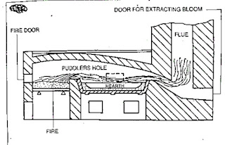
Wrought iron

manufacturing process of wrought iron

. properties and uses of wrought iron

Wrought iron is the purest form of iron. The analysis of wrought iron shows as much as 99.9% of iron.

When heated, wrought iron does not melt, but only becomes pasty and in this form it can be forged to any shape.

Modern methods used to produce wrought iron in large quantities are the

-pudding process

-aston or byers process

Pudding process

Wrought iron is manufactured by refining pig-iron.

By refining pig-iron silicon is removed completely, a greater amount of phosphorus is removed, and graphite is converted to combined carbon.

The above process is carried out in a pudding furnace.

Pudding furnace

This furnace is a coal-fired reverberatory furnace.


The term reverberatory is applied because the charge is not in actual contact with the fire, but receives its heat by reflection from the dome shaped furnace roof.

The product obtained is taken out from the furnace in the form of balls (or blooms) having a mass of about 50kgs.

The hot metal is then passed through grooved rollers which convert blooms into bars called MUCK BARS or PUDDLE BARS.

These bars are cut into short lengths, fastened together in pilers, reheated to welding temparature and again rolled into bars.

Aston process

In this process molten pig iron and steel scrap are refined in a bessemer converter.

The refined molten metal is poured into an open hearth furnace in the iron silicate stage. This removes most of the carbon.

The slag cools the molten metal to a pasty mass which is later squeezed in a hydraulic press to remove most of the slag. Rectangular blocks known as blooms are formed from this mass.

The hot bloom is immediately passed through rolling mills to produce  products of wrought iron of different shapes and sizes.

COMPOSITION OF WROUGHT IRON

Carbon     - 0.02 to 0.03%

Silicon      - 0.1 to 0.2%

Manganese -  0.02 to 0.1%

Sulphur      - 0.02 to 0.04%

Phosphorus - 0.05 to 0.2%

Iron forms of the rest of the content.

PROPERTIES AND USES OF WROUGHT IRON

PROPERTIES

Malleable and ductile. It can neither be hardened not tempered. Tough, shock resistant fibrous structure easy for forge welding. Ultimate tensile strength of about 350 newtons per sq. mm. No effect in salt water. Will not retain the magnetism. Corrosion resistant. Easy to forge wide temparature range 850° c to 1350° c.

USES

Architectural works.

Crane hooks, chain links, bolts and nuts and railway coupling.

Marine works.

Temporary magnets. Core of dynamos.

Agricultural equipment.

Pipes, flanges etc.

SURFACE PREPARATION

Surface carrying dirt, grease, corrosion or mill scale are unsuitable for the direct application of anti corrosion treatment.

The most important factor for any efficient anti corrosion treatment is surface preparation.

The different methods  used for surface preparation are:

--degreasing

-pickling

-blast cleaning

-flame descaling

Degreasing

In degreasing, the surface preparation for anti corrosion treatment is done with a solvent such as:

-white spirits

-carbon tetrachloride

-trichlorethylene

The solvents used in degreasing will create a health hazard. Safety precaution should be taken before using these solvents.

Pickling

Pickling is a chemical method of cleaning.

The surface of the metal is cleaned with dilute sulphuric acid or mixed acids.


Blast cleaning

This is a mechanical method of a cleaning in which the scale and corrosion are removed by a high velocity blast of steel shots or sand particles.If steel shorts are used it is called sand blasting.


Flame descaling

The steel surface which is to be descaled, is heated with an oxy-fuel gas torch with high intensity flames.


This rapid local thermal expansion of  the loosely adhering scale against the relatively un heated base metal causes the scale  to flake off.

This process is excellent for removing rust. Any rust particles converted to powder can  easily be brushed away before commencing to paint. For best results the primer should be applied when the steel is approximately 45°c, that is the temparature at which the hand can hold the steel comfortably.

This method of surface preparation is often specified for the heavy rusted steel work. It is not suitable for light steel work which may buckle and distort because of the intense localized that.


Different Types of cast iron

. different types of cast iron

. properties of each type cast iron

Cast iron is an alloy of iron, carbon and silicon. The carbon content ranges from 2 to 4%.

Types of cast iron

The following are the types of cast iron.

-Grey cast iron

-White cast iron

-Malleable cast iron

-Nodular cast iron

Grey cast iron

This is widely used for the casting of machinery parts and can be machined easily.

Machine bases, tables, slideways are made of cast iron because it is dimensionally stable after a period of  aging.

Because of its graphite content, cast iron provides an excellent bearing and sliding surface.

The melting point is lower than that of steel and as grey cast iron possessses good fluidity intricate casting can be made.

Grey cast iron is widely used for machine tools because of its ability to reduce vibration and minimize tool chatter.

Grey cast iron, when not alloyed, is quite brittle and has relatively low tensile strength. Due to this reason it is  not used for making components subjected to high stress or impact loads.

Grey cast iron is often alloyed with nickel, chromium, vanadium or copper to make it tough.

Grey cast iron is weldable but the base metal needs preheating.

White cast iron

This is very hard and is very difficult to machine, and for this reason,, it is used in components which should be abrasion-resistant.

White  cast iron is produced by lowering the silicon content and by rapid  cooling. When cooled in this manner, it is called chilled cast iron.

White cast iron cannot be welded

Malleable cast iron

Malleable cast iron has increased ductility, tensile strength and toughness when compared with grey cast iron.

Malleable cast iron is produced from White cast iron by a prolonged heat treatment process lasting for about 30 hours.

Nodular cast iron

This is very similar to malleable cast iron. But this is produced without any heat treatment. Nodular cast iron is also known as

NODULAR IORN -DUCTILE IRON- SPHEROIDAL GRAPHITE IRON.

This has good machinability, castability, resistance to wear, low melting point and hardness.

Malleable and nodular casting are used for machine parts where there is a higher tensile stress and moderate impact loading. These casting are less expensive and are an alternative to steel casting.

Cast iron manufacturing process

The pig iron which is tapped from the blast furnace is the crude form of raw material for the cupola, and should be further refined for making castings. This refining is carried out in the cupola furnace which is a small form of  a blast furnace.

Generally cupolas are not worked continuously like blast furnaces but are run only as and when required.

Working of a cupola

For starting a cupola, a COKE fire is lit at the bottom of the cupola. When the fire is established, the furnace is charged with alternate layers of coke and pig iron together with limestone. Steel scrap is also sometimes added depending on the required quality of metal. Adding steel scraps with a lower carbon content reduces the carbon content in the metal. During melting, a blast of air is also introduced into the furnace.

The molten limestone combines with sand and other impurities and floats in a liquid form on the top of the molten metal. It is called slag.

The molten metal sinks to the bottom of the furnace from where it is tapped and collected in ladles. The hot metal.

Uses of pig-iron

.commonly used ferrous metals

. main raw materials used for the smelting of pig-pron and their uses

. constructional features of  a blast furnace


. properties and uses of pig iron

Metals which contain iron as a major content are called ferrous metals. Ferrous metals of different properties are used for various purposes.

The ferrous metals and alloys used commonly are

-pig iron

-cast iron

-wrought iron

-steel and alloy steels

Different processes are used to produce  iron and steel.

Pig-iron obtained by the chemical reduction of iron ore. This process of reduction of the iron ore to pig-iron is known as SMELTING.

The main raw accoutrements needed for producing gormandizer-iron are 

-iron ore

-coke

-flux

IRON ORE

The cheif iron ores used are

-magnetite

-hematite

-limonite

-carbonite

These ores contain iron in different proportions and are 'naturally ' available.

COKE

Coke is the fuel used to give the necessary heat to carry on the reducing action. The carbon from the coke in the form of carbon monoxide combines with the iron ore to reduce it to iron.

FLUX

This is the mineral substance charged into a blast furnace to lower the melting point of the ore, and it combines with the non-metalic portion of the ore to form a molten slag.

Limestone is the most commonly used flux in the blast furnace.

BLAST FURNACE

The furnace used for smelting iron ore is the blast furnace. The product obtained from smelting in the blast furnace is pig-iron. The main parts of the blast furnace are

-throat

-stack

-bosh

-hearth

-double bell charging mechanism

-tuyeres

SMELTING IN A BLAST FURNACE

The raw materials are charged in alternate layers of iron ore, coke and flux in the furnace by means of a double bell mechanism.


The hot blast is forced into the furnace through a number of nozzles called tuyeres.

The temparature of the furnace just above the level of the tuyeres is between 1000°c to 1700° c when all the substance start smelting.

The limestone, which serves as a flux, combines with the non metalic substances in the ore to form a molten slag which floats on the top of the molten iron. The slag is tapped off through the slag hole.

The molten iron is trapped at intervals through a separate tapping hole.

The molten iron may be cast in pig beds or used in other processing plansts of steel making.

PROPERTIES AND USE OF PIG-IRON

Pig iron absorbs varying amount of carbon,silicon, suphur, phosphorus and manganese during the smelting process. A high amount of carbon makes the pig-iron very hard and brittle and unsuitable for making any useful article.

Pig iron is therefore refined and remelted and used to produce other varieties of iron and steel.


Types of plastics

Plastics

. types of plastics

. differentiate between thermoplastics and thermosetting plastics


The dictionary meaning of plastic is 'capable of being easily formed or moulded'.

There are a number of synthetic materials available under the name of plastics.

Plastics have their origin in the chemical synthesis of materials from different sources like

-agriculture

-agriculture and petroleum

-petroleum and coal

-petroleum and mineral

-minerals

Of these, coal and petroleum are mostly used in making plastics

Plastics are divided into three major categories

-thermoplastic

-thermo-setting plastics

-elastomers

Thermoplastics

These are formed into shape by the application of heat and pressure. They soften when heated, and become solid agian when cooled. There is no chemical change in the moulding operation.

Thermoplastics are

-nylon

-polythene

-polypropylene

-polystyrene

-poly vinyl chloride

-acrylic resin

-cellulose

Nylon(polymide)

It is strong, tough and of light weight. It has a good abrasion resistance, and resistance to chemicals, fuels and oils.

It is used for making light engineering components such as gears, bushes, bearings, machine slides, rollers, brush bristles etc.

Polythene

There are two types

-low density polythene

-high density polythene

Polythene is cheap. It has high resistance to water, oils and chemicals. It can also withstand sizable temparature changes.

Low density polythene is used for making bags, sacks for package, dust bins, toys and house wares etc.

High density polythene is used for large moulded containers, bottles, milk crates, pipes and better quality House-wares.

Polypropylene

It is the lightest among plastics. It is tough and has high resistance to heat and chemicals.

It is used for making automobile accelerator pedals,suitcases, hospital equipment, ropes and twines etc.

Polystyrene

It is the cheapest, had good resistance to water, oils and alkalis. But it disolves in solvents.

It is used for making thin-walled containers for dairy products  and food stuffs. It is also used for fridge liners, spools, cassettes and cartridges for taps and photographic films. It is also used  in vaccum cleaners

Poly vinyl chloride

It possesses good physical strength, and has good resistance to water and chemicals. It is a good electrical insulator.

PVC may be flexible or rigid.

Rigid PVC is used for pipes and fittings, wall cladding, electrical conduits, gramaphone records, bottles for edible oils etc.

Flexible PVC is used for cable and wire insulation, floor and wall covering, tents and hose-pipes etc.

Acrylic resin

It is popularly known as perspex. It possesses exceptional stability in outdoor weather, resulting wide use in sings and displays and light fittings. At room temparature, it is rigid. It is transparent surface, gloss, chemical resistance and moldability.

There are used for making toys, cutlery handles, electrical parts, knobs, electrical insulating taps etc.

Cellulose nitrate, well known by the trade name of 'celluloid' is available in a variety of colours. It is still popularly used for spectacle frames, fabric coatings etc.

Thermo setting plastics

These are some plastics that undergo chemical changes during processing to become permanently insoluble and infusible.

There are

-phenolics

-aminos

-epoxy

-polyster resins

Phenolics

There are based on phenol-formaldehyde resins and are often called as Bakelite.

Bakelite is available mostly in brown and black colours. It is a good electrical insulator. Bakelite shows good resistance to water, acide and most solvents. It is rigid, and has  low thermal conductivity.

It is used for saucepans and kettle handles, terminal blocks, electrical insulator. Bakelite shows good resistance to water, acid and most solvents. It is rigid, and has  low thermal conductivity.

It is used for saucepans and kettle handles, terminal blocks, electrical swith -gears, cooker control knobs, voltage regular covers etc.

Aminos

Aminos are the products of a combination of urea or melamine with formaldehyde to form urea formaldehyde and melamine formaldehyde.

Aminos are available in an unlimited range of colours. They have good resistance to oil, grease, solvents and heat. They have good strength, and are hard, rigid and durable. They are free from odour and taste.

Urea formaldehyde is widely used in domestic electrical fittings like switch -covers, plug tops, bottle tops for scent etc.

Epoxy

Epoxy adhesive are used as casings for pipe fittings, electrical and other equipments.

They are also used as low pressure laminates such as printed circuit boards, boat bodies etc.

Polyster resins

Polyster resins are used with fibre  glass for making glassfibre reinforced plastics.

Elastomers

These are materials that can be stretched repeatedly to atleast twice their original length, which will return with force to their approximate original length when the immediate stress is released.

Elastomers are made with modified thermoplastics and rubber, natural and synthetic.

Elastomers are used for gaskets, moulds, foam mattresses and insulations.


LATHE ACCESSORIES -4 JAW AND 3 JAW CHUCK

 Lathe accessories -4 jaw and 3 jaw chuck

. corridor of a 4 jaw chuck and 3 jaw chuck

.features of a 4 jaw chuck and 3 jaw chuck


 4 jaw chuck

The four jaw chuck is also called as independent chuck, since each jaw can be acclimated singly; work can be trued to within0.001"or0.02 mm delicacy using this chuck. 


 This type of chuck is much more heavily constructed than the tone- centering chuck, and has much lesser than holding power. Each jaw is moved singly by a square thread screw. The jaws are reversible for holding large periphery jobs. The independent 4 jaw chuck has four jaws, each working singly of the others in its own niche in the chuck body and actuated by its own separate square threaded screw. By suitable adaptation of the jaws, a workpiece can be set to run either true or eccentric as needed. 

 To set the job for the alternate time, it can be trued with the help of a dial test index. 

 The check on the workpiece should be carried out near the chuck and repeated as far from it as the workpiece permits, to insure that the work isn't held in the chuck at an angle to the axis of gyration. 

The independent adaptation also provides the installation of designedly setting the work off- centre to produce an eccentric workpiece. 

 The corridor of a 4 jaw chuck are 

- reverse plate 

- body 

- jaws 

-square threaded screw shaft 

 Back plate

 The reverse plate is fastened to the reverse of the body by means of allen screws. It's made out of cast iron/ sword. Its drag is phased to suit the taper of the spindle nose. It has a crucial- way which fits into the crucial handed on the spindle nose. There's a step in front and on which the thread is cut. A threaded collar, which is mounted on the spindle, locks the chuck by means of the thread, and locates by means of the taper and key. Some chucks don't have back plates. 

 Body

 The body is made out of cast iron/ cast sword and the face is honey- hardened. It has four openings at 90 ° piecemeal to assemble the jaws and operate them. Four screw shafts are fixed on the fringe of the body by means of cutlet poins. The screw is rotated by means of chuck key. The body, concave in the cross section, has equi-spaced indirect rings handed on the face, which are marked by numerical figures. Number 1 starts in the middle, and increases towards the fringe. 

 Jaws

 Jaws are made out of high carbon sword hardened and tempered, which slide on the opening of the body. These jaws are reversible for holding concave work. 

The aft side of the jaws are square threaded which hepls in fixing the jaws with the operating screws. 

 Screw shaft 

 The screw shaft is made out of high carbon sword, hard ened, tempered and ground. The top portion of the screw shaft is handed with a squre niche to accommodate the chuck key. On the body portion, a left hand squre thread is cut in the middle of the screw shaft, a narrow step is made and held by means of cutlet legs. The cutlet legs permit the screws to rotate but not to advance

3 jaw chuck

 The 3 jaw chuck is also known as a tone centering chuck. The maturity of the chucks have two sets of jaws for holding internal and external periphery. Only perfect round work with inversely spaced apartments separable by three should be held in a 3 jaw chuck. 


 From the construction of a 3 jaw chuck is seen that the scroll not only clamps a element in place, it also locates the element. This is unnaturally a bad practice, since any wear in the scroll and or the jaws impairs the delicacy of position. Further there's no means of adaptation possible to compensate for this wear. 

 The jaws of this type of chuck aren't reversible, and seperate internal and external jaws have to be used. 

The corridor of a 3 jaw chuck are 

 Back plate 

 Body 

 Jaws 

Crown wheel 

 Pinion 

 Back plate

 The reverse plate is fastened at the reverse of the body by means of allen screws. It's made out of cast iron. Its drag is phased to suit the taper of the spindle nose. It has a crucial- way which fits into the crucial handed on the spindle nose. There's a step in the front on which the thread is cut. The threaded collar, which is mounted on the spindle, locks the chuck by means of the thread and locates by mean of the taper and the key. 

 Body

 The body is made out of cast sword, and the face is hardened. It has three opening 120 ° piecemeal to assenble the jaws and operate them. Three pinions are fixed on the fringe of the body to operate the jaws by means of a chuck key. It's concave in its cross section. A crown wheel is housed inside the body. 

 Jaws

 The jaws are made out of high carbon sword, hardened and tempered, which slide on the opening of the body. Generally there are two sets of jawsviz. 1 external jaws and 2 internal jaws. External jaws are used for holding solid workshop. Way on the jaws increase the setting range. The aft side of the jaws is cut with scroll thread. Each jaw is numbered in a successional manner, which helps in fixing the jaws in the corresponding numbered places. 

Crown wheel

 The crown wheel is made out of allow sword, hardened and tempered. On one side of the crow wheel a scroll thread is cut to operate the jaws, and the other side is phased on which the bevel gear teeth are cut to mesh with pinion. When the pinion is rotated by means of a chuck key, the crown wheel rotates, therefore causing the jaws to move inward or outward, depending upon the gyration. 

 Pinion

 Pinion ia made out of high carbon sword, hardened and tempered. It's fitted on the fringe of the body. On the top of the pinion a square niche is handed to accommodate the chuck key. It has a phased portion on which bevel gear teeth are cut, which match with the crown wheech


Comparison between 3 jaw chuck and 4 jaw chuck

3 jaw chuck

 Only cylidrical, hexagonal work can be held. 

 Internal and external jaws are available. 

 Lower absorbing power. 

 Depth of cut is comparatively less. 

 Heavier jobs can not be turned. 

 Workpieces can not be set for eccentric turning. 

Concentric circles aren't handed on the face. 

 Delicacy decreases as the chuck get worn out. 

 4 jaw chuck

 A wide range of regular and irregular shapes can be held. 

Jaws are reversible for external and internal holding. 

 Setting up of work is delicate 

 Further absorbing power. 

 Further depth of cut can be given. 

 Heavier jobs can be turned. 

 Workpieces can be set for eccentric turning. 

 Concentric circles help for approximate setting of jaws. 

 There's no loss of delicacy as the chuck gets worm out 

 Merits of 4 jaw chuck

 A wide range of regular and irregular shapes can be held. 

 Work can be set to run concentrically or eccentrically at will. 

 Has considerible absorbing power, and hence heavy cuts can be given. 

The jaws are reversible for internal and external work. 

 Work can be readily performed on the end face of the job. 

 There's no loss of delicacy as the chuck gets wornout. 

De-merits of a 4 jaw chuck

Workpieces must be collectively set. 

 The gripping power is so great that fine work can be fluently damaged during setting. 

 Merits of 3 jaw chuck

 Work can be set easy 

A wide rage of spherical and hexagonal work can be held. 

 Internal and external jaws are available. 

De-merits  of a 3 jaw chuck

 Delicacy drop as chuck becomes worn out. 

 Run out can not be corrected 

 Only round hand hexagonal factors can be held. 

 When accurate setting or concentricity with a being periphery is needed, a tone centering chuck isn't used. 


LATHE-FEED MECHANISAM OF LATHE

 Feed mechanism of lathe

. the parts of the feeding mechanism

. functional features of the feeding mechanism


Feed mechanism

The feed mechanism of a lathe enables automatic feeding for the tool longitudinally and transversely as needed. By automatic feeding the finish on the work will be better, the feeding of the tool will be at a uniform by continuous rate and it takes less time to finish the operation while manual labour is avoided.


The feed mechanism comprises

Spindle gear

Tumbler gear unit

Fixed stud gear

Change gear unit

Quick change gear box

Feed shaft/lead screw

Apron mechanism

The proportionate tool movement for each revolution of work is achieved through all the above units of the feed mechanism.

Spindle gear

The spindle gear is fitted to the main spindle, and it is outside the headstock casting. It revolves along with the main spindle.

Tumber gear unit

The tumbler gear unit itself is of three gears, having the same number of teeth and  it contacts the  spindle gear to the fixed gear. It is also called the reversing gear unit as it is used to change the direction of feed of the tool for the same direction of rotation of the spindle. It can be engaged and disengaged with the fixed stud gear by  the operation of the hand lever provided in the unit.


The fixed stud gear

The fixed stud gear gets the drive from the main spindle gear through the tumbler gear unit and runs at the same number of revolutions per minute as the spindle gear  on most lathes.

Change gear unit

The fixed stud gear transmits its drive through a change gear unit to the quick change gear box. The change gear units has provision for changing the driver the driven and the idler gears from the set of change gears available for the purpose of  feed chaging as an additional unit.


Quick change gear box

The quick change gear box is provided with levers outside the box casting, and by shifting the levers, different gears are brought in mesh so that different feed rates can be given to the tool. A chart listing the different feed rates for the different positions of the levers is fixed to the casting, and by refering to the table, the levers may be engaged in position for the required feed rate.


The feed shaft

The feed shaft gets it drive from the quick change gear box, and through the apron mechanism, the  rotary movement of the feed shaft is converted into the linear movement of the tool.

The apron mechanism

The apron mechanism has the arrangement for transmitting the drive from the feed shaft to the saddle for longitudinal movement of the tool or to the cross slide for the transverse movement of the tool


-

Lathe cutting tools-toola angles and their functions

 Lathe cutting tools-tool angles and their functions

. functions of angles and clearance given on the cutting tools

. the angles of a lathe cutting tool

. the characteristics of a rake angle

. the characteristics of  a clearance angle


The tool acts like a wedge during turning. The wedge shaped cutting edge penetrates into the work and removes the metal. This necessitates the grinding of a tool cutting edge to a wedge shape. When we sharpen a pencil with a pen knife by trial and error, we find that the knife must be presented to the wood at a definite angle, if success is to be achieved.


If, in the place of a wooden pencil, a piece of soft metal such as brass is cut, it will be found that the cutting edge gets crumbled. For tha blade to cut the brass successfully, the cutting edge must be ground to a less acute angle.


Angles ground on a lathe cutting tool

All the angles may not be located or found in every tool. As an example a roughing tool is chosen. The angles and clearances ground on this tool are

-approach angle(1)

-trail angle(2)

-top rake angle(3)

-side rake angle(4)

-front clearance angle(5)

-side clearance angle(6)


Approach angle

This is also known as side cutting edge angle. This is ground on the side of the cutting tool. The cutting wil be oblique while cutting. The angle ground may range from 25° to 40° but as a standard a 30° angle is normally provided. The oblique cutting the advantages over the orthogonal cutting, in which the cutting edge is straight. More depth of cut is given in the case of oblique cutting, since, when the tool is fed to the work, the contact surface of the tool increases gradually as the tool advances, whereas in the case of the orthogonal cutting, the length of the cutting edge for the given depth fully contacts the work from the begining itself which gives a sudden maximum load on the tool face. The area over which heat is distributed is greater in oblique cutting.


Trail angle

It is also known as end cutting edge angle, and is ground at 30° to a line perpendicular to the aixs of the tool, as illustrated.


The approach angle and trail angle ground form the wedge angle of 90° for the tool.

Top or back rake angle

The rake angle ground on a tool controls the geometry of chip formation. Thereby, it controls the cutting action of the tool. The top or back rake angle of the tool is ground on the top of the tool, and it is a slope formed between the front of the cutting edge and the top of the face. If the slope is from the the front towards the back of the tool, it is known as a positive top rake angle, and if the slope is from the back of the tool towards the front of the cutting edge, it is known as a negative back rake angle.


The top rake angle may be ground positive, negative or zero according to the material to be machined. When turning soft, ductile materials, which form curly chips, the positive top rake angle ground will be comparatively more than for turning hard brittle metals

When turning hard metals with carbide tools, it is the usual practice to give a negative to rake. Negative top rake tools have more strength than tools with positive top rake angles.

Side rake angle

A side rake angle is the slope between the side of the cutting edge to the top face of the tool width wise. The slope is from the cutting edge to the rear side of the tool. It varies from 0° to 20°,according to the material to be machined.


The top and side rake, ground on a tool control the  chip flow, and this results in a true rake angle which is the direction in which the chip that shears away from the work passes.

Front clearance angle

It is the slope between the front of the  cutting edges to a line perpendicular to the axis of the tool drawn downwards which is known as the front clearance angle. The  slope is from the top  to the bottom of the tool, and permits only the cutting edge to contact the work, and avoids any rubbing action. If the clearance ground is more, it will weaken the cutting edge.


Side clearance angle

The clearance angle is the slope formed between the side cutting edges of the tool with a line perpendicular to the tool axis drawn downwards at  the side cutting edge  of the tool. The slope is from the top of the side cutting edge to the bottom face. This is also ground to prevent the tool from rubbing with the work, and allows only the cutting edge to contact the work during turning. The side clearance angle needs to be increased when the Fred rate is increased. When grinding rake and clearance angles, it is better to refer to the standard chart provided with the recommended values and grind. However, then actual operation will indicate the performance of the tool, and will indicate to us, if any modifications are needed for the angles ground on the tool.


Side relief angle

This angle is ground on parting and undercut tools on both sides. This will provide for the width of the cutting edge to be slightly broader than the back of the cutting edge.


A side relief angle permits clearance between the sides of the tool and the groove walls, formed by the plunging action of the tool, thereby, preventing the tool from getting jammed in the groove, causing breakage. The relief is kept as  minimum as possible. Too much of relief will weaken the tool cutting -edge tail, and also permit the chips to clog in the gap, in both cases causing the tool to break. Side relief is also provided sometimes to the main cutting edge of the facing tool, permitting the cutting point only to perform the operation, whenn the tool axis is set perpendicular to the lathe axis. The side relief angle normally does not exceed 2°.

Relationship between rake angle and wedge angles


The rake angle, clearance angle, and the wedge angle have close relationship for efficiency in cutting. Excessive rake angle reduces the wedge angle, which helps in good  peneteration, and it is particularly useful for cutting soft metals. A decreased wedge angle weakens the tool strength. Therefore, for cutting hard metals, the rake angle is zero or negative. The clearance angle is generally fixed depending on the geometry of the surface being cut.

LATHE-TYPES OF CUTTING TOOlS

 Types of cutting tools for lathe

. the different shapes of cutting tools used for lathe operations

. the characteristics and uses of different shapes of lathe tools.

Cutting tool -classification

-single point cutting tools

-multi-point cutting tools

Form tools.


Single point cutting tools have one cutting edge which performs the cutting action. Most of the lathe cutting tools are single point cutting tools.


Single point cutting tools used on lathes may be grouped into:

-side-cutting tools

-end -cutting tools


Side cutting edge tools have their cutting edges formed on the side of the cutting tool, and are used on lathes for most of the operations. They are again classified as right hand tools and left hand tools. A right hand tool operates from the tailstock and towards the headstock, and a left hand tool operates from the headstock end towards the tailstock. The cutting edges is formed accordingly.


End -cutting tools have their cutting edge at the front end of the tools and are used on lathes for plunge opertations.

Multi-point cutting tools

These tools have more than one cutting edge and remove metal from the work simultaneously by the action of all the cutting edges. The application of multi point cutting tools on the lathe is mostly done  by holding the tool in tailstock and feeding it to the work.


Form tools

These tools reproduce on the work the form and shape of the cutting edges to which they are ground. Form tools perform the operations on the work by the plunging action, and are fixed on the tool post, square to the axis of the work, and are fed by the cross slide. They may have their cutting edges formed on square of rectangular section tool blanks acting radially. The form tools may be either circular form tools or tangential form tools. They may require special holders to which they are fixed and the holder themselves are clamped on the tool posts for the operations.


LATHE CUTTING TOOL TYPES

Solid type tools

Brazed type tools

Inserted bits with holders

Throw-away type tools

Solid tools

These are tools having their cutting edges ground on slid bits of square rectangular and round cross -sections. Most of the lathe cutting tools are of the solid type, and high carbon steel and high speed steel tools depend upon the capacity of the machine, the type of tool post and the nature of the operation.


Inserted bits with holders

Solid high speed steel tools are costly;hence, they are sometimes used  as inserted bits. These bits are small in sizes, and are inserted in the holes of the holder. These holders are held and clamped in the tool posts to carry out the operations. The disadvantage in this type of tools is that the rigidity of the tool is poor


Brazed tools

These tools are made up of two different metals. The cutting portions of these tools are of cutting tool materials, and the body of the tools do not possess any cutting ability, and are tough. Tungsten carbide tools are mostly of the brazed type. Tungsten carbide bits of  square, rectangular and triangular shape are brazed to the tips of  the shank. The tips of the shank metal pieces are machined on the top surface according to the shape of the fits so as to accommodate the carbide  bits. These tools are economical, and give better rigidity for the tools than the inserted bits clamped in the tool-holder. This is applicable to high speed steel brazed tools also.


Throw-away type tools

Carbide brazed tools when blunt or broken need grinding which is time absorbing and expensive. Hence, they are used as throw -away inserts in mass production. Special tool-holders are needed and the carbide bits of rectangular, square of triangular shapes are clamped in the  seating faces and machined on this type of special holders.


The seating faces are machined in such a way that the rake and clearance needed for the cutting bits are automatically achieved when the bits are clamped.

Lathe cutting tool shapes

Lathe cutting tools are available in a variety of shapes for performing different operations. Some of the lathe cutting tools generally used are:

-facing tool

-knife edge tool

-roughing tool

-round nose finishing tool

-broad nose finishing tool

-undercutting tool/parting off tool

-external threading tool

-boring tool


LATHE-CUTTING TOOl MATERIALS

 Cutting tool materials

. qualities of good cutting tool material

. characteristics of cold hardness, red hardness and toughness

. the factors to be remembered when selecting tool material

. the different tool materials

. the characteristics of different tool materials


Cutting tool materials

Tool materials should be :

-harder and stronger than the material being cut

-tough to resist shock loads

-resistant to abrasion thus contributing to long tool life.

Cutting tool material should possess the following qualities.

- cold hardness

-red hardness

-toughness

It is the amount of hardness possessed by a material at normal temparature. Hardness is the property by which it can cut/scratch other metals. When hardness increase, brittleness also increases, and a material, which has tooo much of cold hardness, is not suitable for the manufature of cutting tool.

Red hardness

It is the ability of a tool material to retain most of its cold hardness properly even at very high temparature. While matching, the friction between the tool and the work, the tool and the chips, causes heat to be generated, and the tool loses its hardness, and its efficiency to cut diminishes. If  a tool maintains its cutting efficiency even at increased temaprature during cutting, it can be said that it possesses the red hardness property.

Toughness

The property to resist breakage due to sudden load that results during metal cutting is termed as 'toughness '. This will reduce the breakage of the cutting edges of tools.

The following factors are to be considered, when selecting a tool material.

-material to be machined

-condition of the machine tool (rigidity and efficiency )

-the total quantity of production and the rate of production

-the diemensional accuracy required and the quality of surface finish

-the amount of coolant applied and method  of application

-condition and form of material to be machined

Grouping of tool material

The three groups under which tool materials fall are

-ferrous tool materials

-non ferrous tool materials

-non metallic tool materials

Ferrous tool materials

These materials have iron as their cheif constituent. High carbon steel (tool steel) and high speed steel belong to this group.

Non ferrous tool materials

These do not have iron, and they are formed by alloying elements like tungsten, vanadium and molybdenum stelite belongs to this group.

Carbides

These materials are also non ferrous. They are manufactured by powder metallurgy technique. Carbon and tungsten are the chief alloying elements.

Non metallic materialbit.

These tool materials are made out of non metals. Ceramics and diamonds belong to this group.

Higj carbon steel is the first tool material introduced for manufacturing cutting tools. It has poor red hardness property, and it loses its cutting efficiency very quickly. Alloying elements like tungsten, chromium andvanadium, are used to produce high speed steel tool material. Its red hardness property is more than that of high carbon steel.

High speed steel is used for making solid tools, brazed tools and inserted bits. It is costlier than the high carbon steel. Carbide cutting tools can retain their hardness at very high temparature, and their cutting efficiency is higher than that of high speed steel. Due to its  brittleness and cost, a carbide tool cannot be used as a solid tool. It is used as a brazed tool and throw away tool bit.


LATHE PARTS-TAILSTOCK AND MAIN SPINDLE

 Lathe parts-Tailstock and Main spindle

. the parts of a tailstock

. uses of tailstock

. functioning of a tailstock

. functions of the main spindle

. features of main spindle


Tailstock

It is sliding unit on the bed ways of the lathe bed. It is situated on the right hand side of the lathe. It is made in two parts namely tha base and the body. The base bottom is machined accurately and has 'V' grooves corresponding to the bed-ways. It can slide over the bed and can be clamped at any position on the bed by means of the clamping unit. The body of the tailstock is assembled to the base. Gradutions are marked on the rear end of the base and a zero line is marked on the body.

When both zero lines coincide the Axis of the tailstock is in line with the axis of headstock.

The body and base are out of cast iron. The parts of a tailstock are

-base(a)

-body (b)

-spindle (c)

-spindle locking lever(d)

-operating screw rod(e)

-operating nut(f)

-tailstock hand wheel (g)

-key (h)

-clamping nut(i)

-adjusting screws (j)


Functioning of a tailstock

By rotating the hand wheel, the barrel can be moved forward or backward. The barrel can be locked in any required position. The hollow end of the barrel at the front is provided with the a morse taper to accommodate the cutting tools with a  taper shank. Graduations are sometimes marked on the barrel to indicate the movement of the barrel. With the help of the adjusting screws, the body can be moved over the base laterally, and the amount of movement may be read approximately refering to the gradutions marked. This arrangement is to offset the centre of the tailstock as required for taper turning.

Purpose of the tailstock

To accommodate the dead centre to support lengthy work to carry out lathe operations.


To hold cutting tools like drills, reamers, drill chucks provided with taper shank.


To turn external taper by offsetting the body of the tailstock tailstock

ect to the base.


MAIN SPINDLE

The main spindle is fitted on the headstock. It has facilities for holding and rotating the Work-holding devices, and, therefore, the work itself.

Features

The main spindle is hollow so as to accept the bar stock and also to reduce the weight. It is hardened, ground and super finished to high accuracy. In the assembled condition in the headstock, its Axis is perfectly parallel to the lathe bed-ways. The main spindle is carried and supported by anti -frictional ball, roller, thrust and taper roller bearing according to the design of the machine.

The portion of the main spindle, which is outside the headstock box section, is known as the spindle nose.


It is bored internally to a morse taper to accept the adapter sleeve which, in turn, accommodates the live centre. The periphery of the spindle nose has provisions for mounting the work-holding devices.

TYPES OF SPINDLE NOSES AND THEIR FEATURES

Plain threaded spindle nose


Long taper spindle nose


Short taper spindle nose


Spindle nose  mounting with tapered matching surfaces are preferred as they are self aligning, and compensate for normal wear without much loss  of accuracy.

The spindle located in bearing enables to have its axis and the axis of the work -holding device mounted upon it parallel to the bed slideways of  the machine both in the horizontal and vertical planes.

The main spindle, its bearing and the headstock casting are sufficiently rigid to prevent the mass of the work and the Work-holding device, together with the cutting forces, from deflecting the spindle axis from its 

LATHE PARTS-CARRIAGE AND TOOL POST

Lathe parts- carriage and tool post

.the function of a carriage

. the parts of a carriage

. commonly used types of tool post

. features of different types of tool posts


Carriage is the feature of a lathe that provides the method of holding and moving the cutting tool. It can be locked at any desired position on the lathe bed. It consists of two major parts namely, apron and saddle.


Apron

The apron is botled to thee  front of the saddle. It contains mechanisms for moving and controlling the carriage. The main parts of an apron are:

-traversing handweel

-feed lever

-feed selector

-lead screw engagement lever


Saddle

It is a 'H' shaped casting having 'V' guide grooves at the bottom face, corresponding to the lathe bed-ways for mounting on the lathe bed and for sliding.

Parts of a saddle

Cross -slide

The cross -slide is  mounted on the top of the saddle, and it provides cross movement for the tool. This is fitted at right angles to  the bed and is moved by means of a screwed spindle, fitted with a  handle. A graduated collar, mounted on the screw rod along with the hand wheel, helps to set the fine movements of the cross-slide.


Compound rest

The compound rest is fitted on the top and to the front of the cross-slide. The compound rest  can be swivelled horizontally through 360°.

Top slide

The top slide is fitted on the top of the compound rest. It supports the tool post which holds the cutting tool. The top slide provides a limited horizontal movement for the cutting tool.

By swiveling the compound rest, the top slide can be set at an angle to the cross-slide.

Usually the compound rest is set in such a way that  the top slide is at right angles to the cross-slide.


TOOL POST 

The tool post holds and fimly supports the tool  or tools. The tool post is fitted on the top slide.


The commonly usee types of  tool post are

-American type tool post or single way tool post indexing type tool post  or squre tool post

-quick change tool post.

Single way tool post

It consists of a circular tool post bdy and a pillar with a slot for accommodating the tool or tool-holder. A ring base, a roker arm(boat piece) and a tool -clamping screw complete the assembly of this type of tool post.


The tool is positioned on the boat piece and clamped. The centre  height of the tool tip can be adjusted with the help of the rocker arm and the ring base. Only one tool can be fixed in this type of tool post. The rigidity of the tool can be fixed in this type of tool post. The rigidity of the tool is less as it is clamped with only one bolt.

Indexing type tool post

It is also called as squre tool post or a four-way tool post. Four tools can be fixed in this type of tool posts, and any one can be brought into the operating position, and the square head is clamped with the help of the handle lever.By loosening the handle lever, the next tool can be indexed and brought in to the operating position. The indexing may be manual or automatic.


The advantages

Each tool is secured in the tool post by more than one bolt, and, therefore, the rigidity is more.

Frequent changing of the tool for different operations need not be done as all the four tools can be clamped at the same time.

The disadvantage is thet skill is required to set the tools, and it takes more time to set to the centre height.

Quick change tool post

Modern lathes are provided with this type of tool posts. Instead of changing the tool, the tool holder is changed in which the tool is fixed. This is expensive and requires a number of tool-holders. But it can be set to the centre height easily, and has the best rigidity for the tool.